
Sainsmart Genmitsu 3020-Pro Max

Video index
00:00 Introduction
01:09 Working area
01:20 Controller pcb
02:35 Power supply earthing
02:51 Assembly
05:02 Offline controller
06:00 V bits
06:17 Gcode example
06:53 Software
06:59 CH340 device driver
07:10 Candle
07:24 Com port
07:37 Homing
08:05 Grbl configuration
08:32 Max travel settings
08:47 Soft limits
09:30 Spindle speed
10:02 Stepper motor config
10:15 Spoilboard design
11:22 Spoilboard surfacing
11:59 PCB milling
12:19 Flatcam
12:47 Height probing
12:55 Probe opto isolator
14:00 Candle height map
15:33 Pcb drilling
16:22 Pcb outline milling
17:06 Copper celtic knot
17:19 Dust shield
18:19 Aluminium milling tests
18:47 Mdf test
19:14 Aluminium – Fusion
20:05 More aluminium tests
20:44 Conclusions
Video script
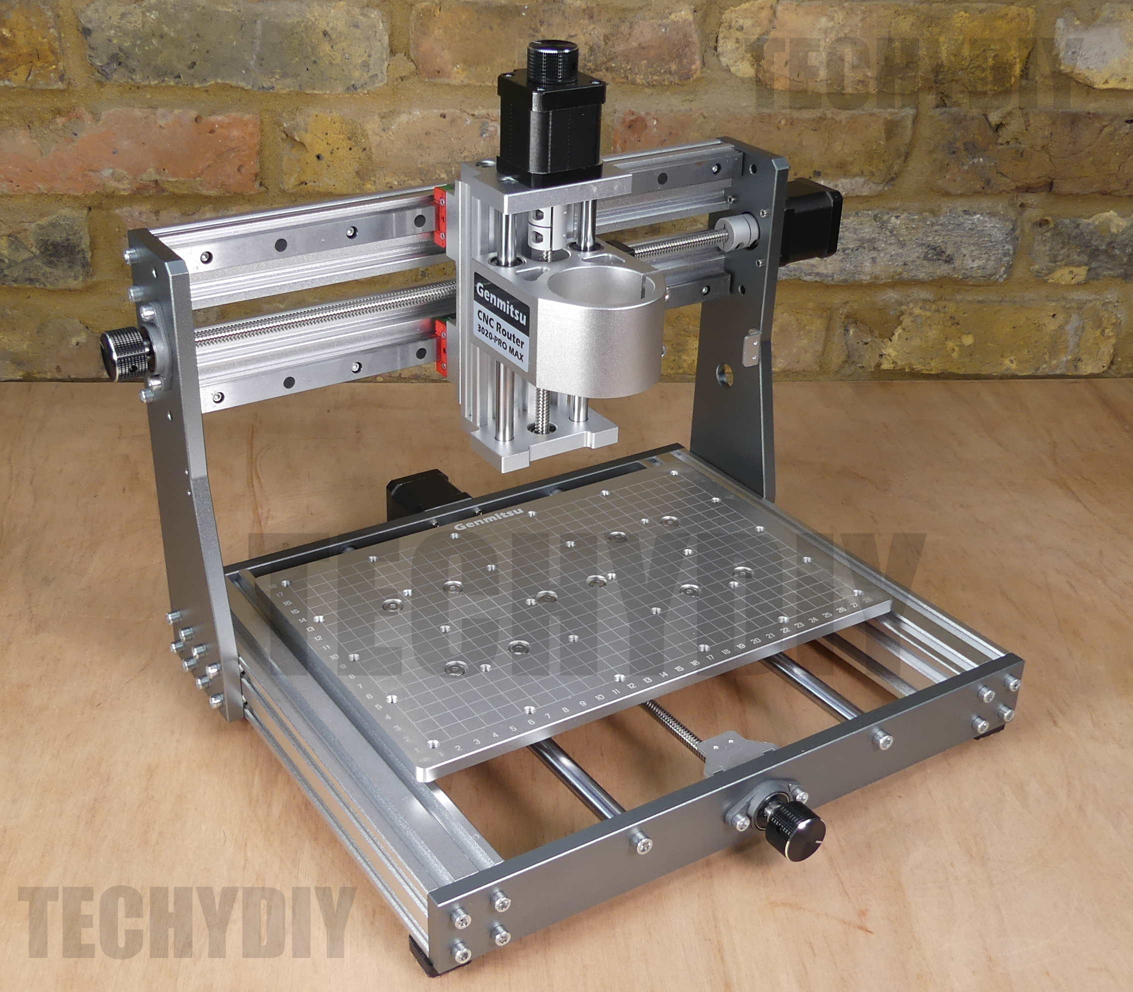
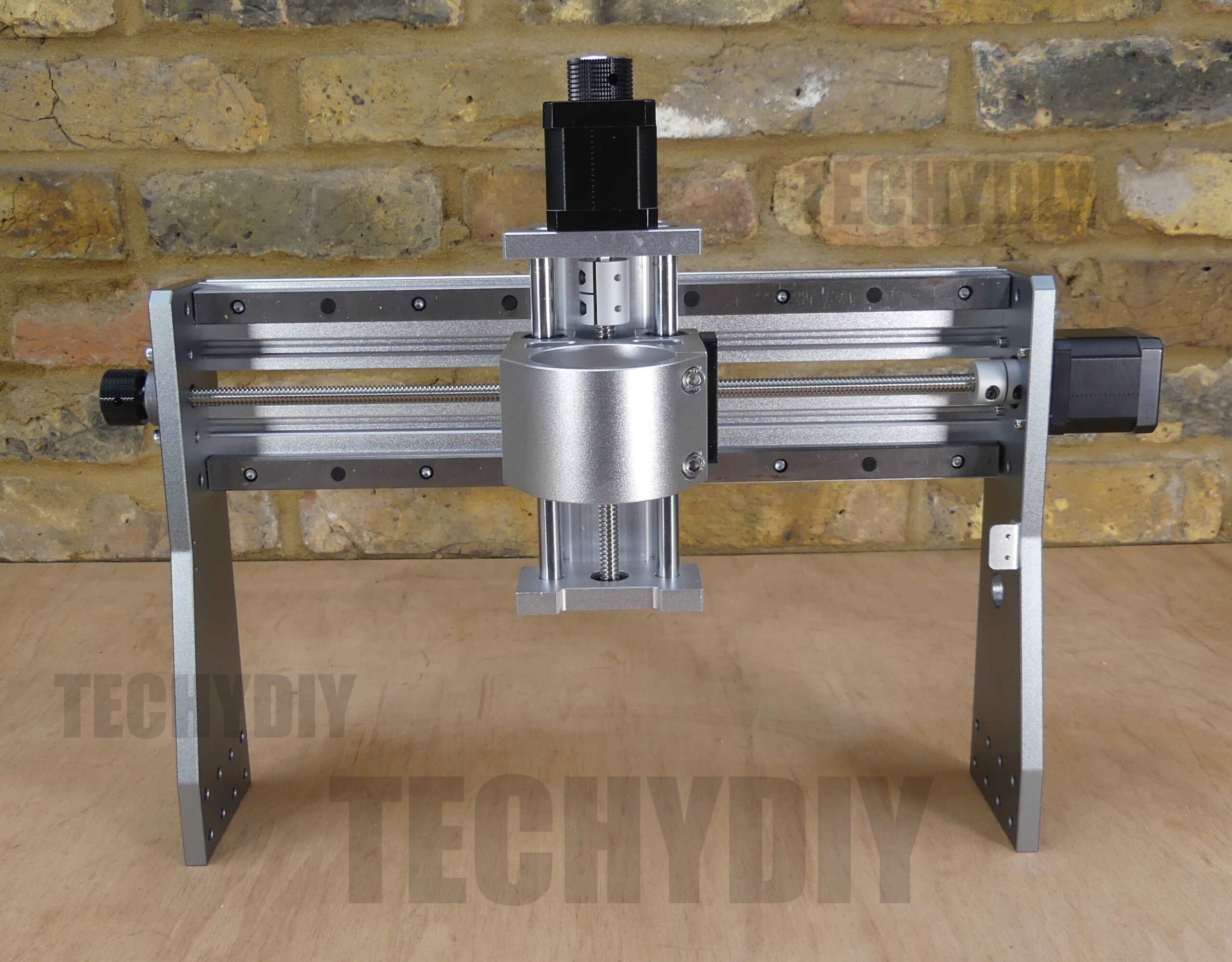
This is the Sainsmart Genmitsu 3020 Pro Max
It’s a 3 axis cnc Machine
which was supplied free of charge for this review.
It’s similar to a 3018 pro type machine, with upgraded components
Sainsmart advertise it as suitable for metal carving,
so I will be testing that later on in the video.
The machine is supplied in several parts
The base
The gantry
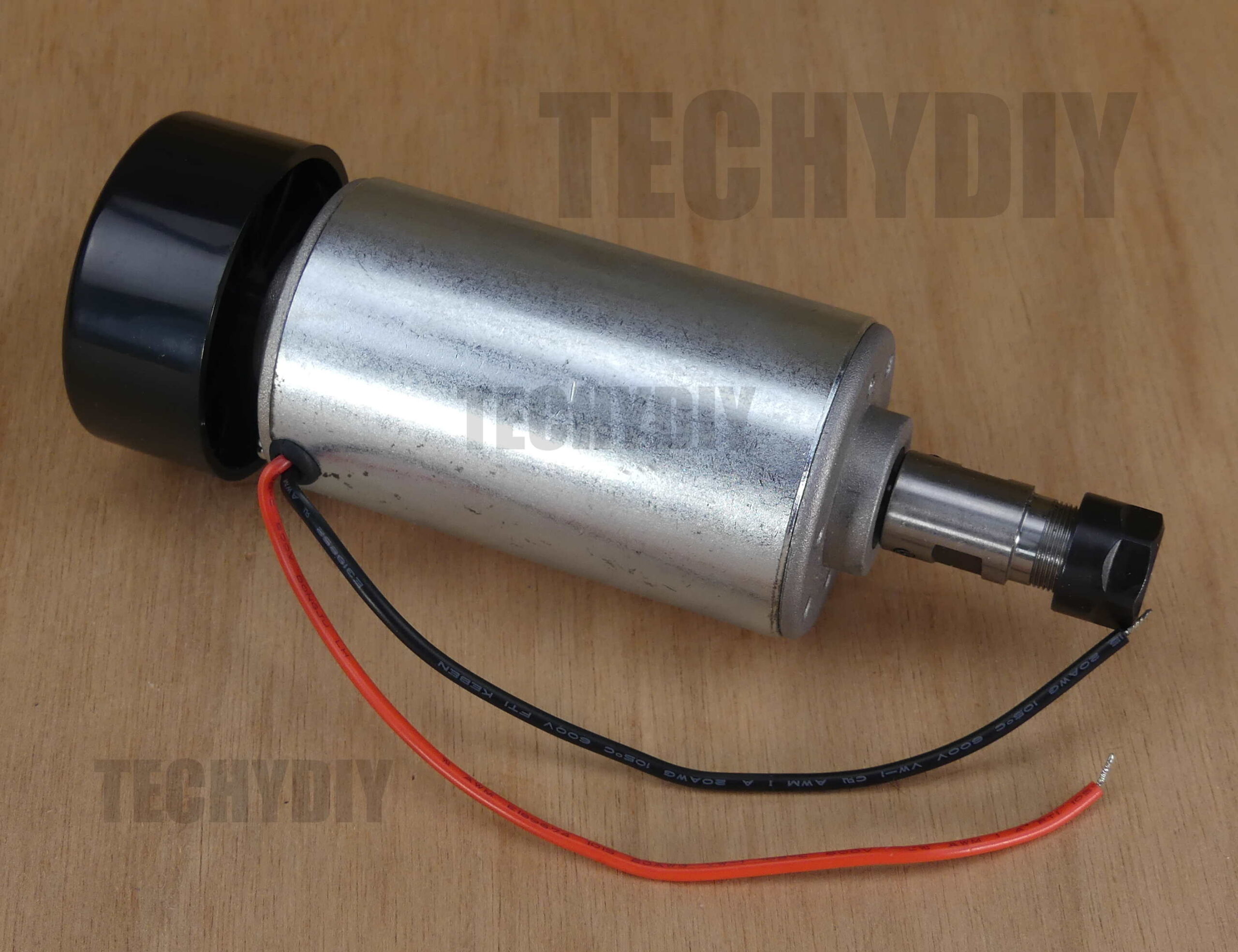
A 52mm 300w spindle motor
A 3 axis controller
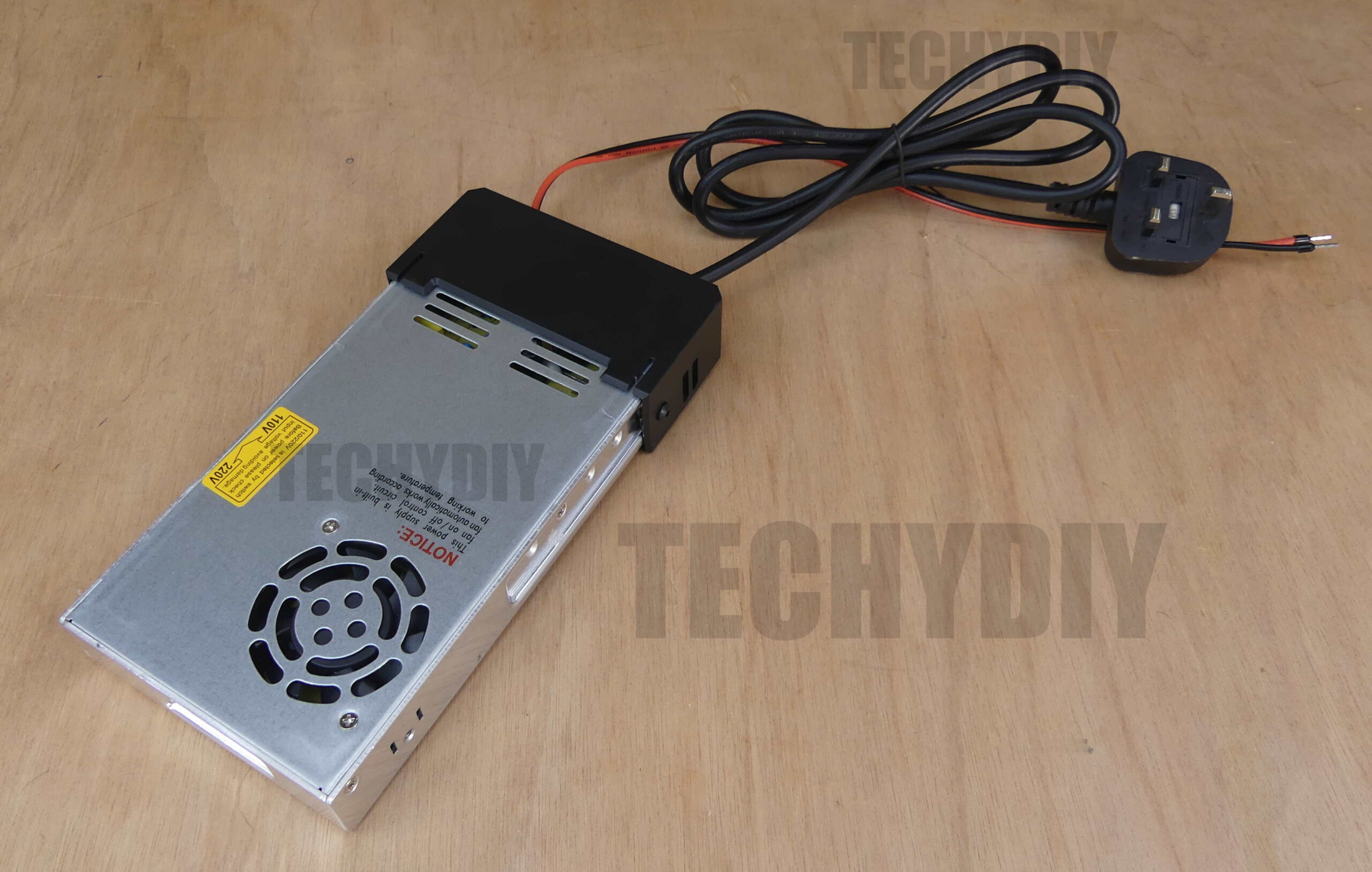
A 48v Power supply
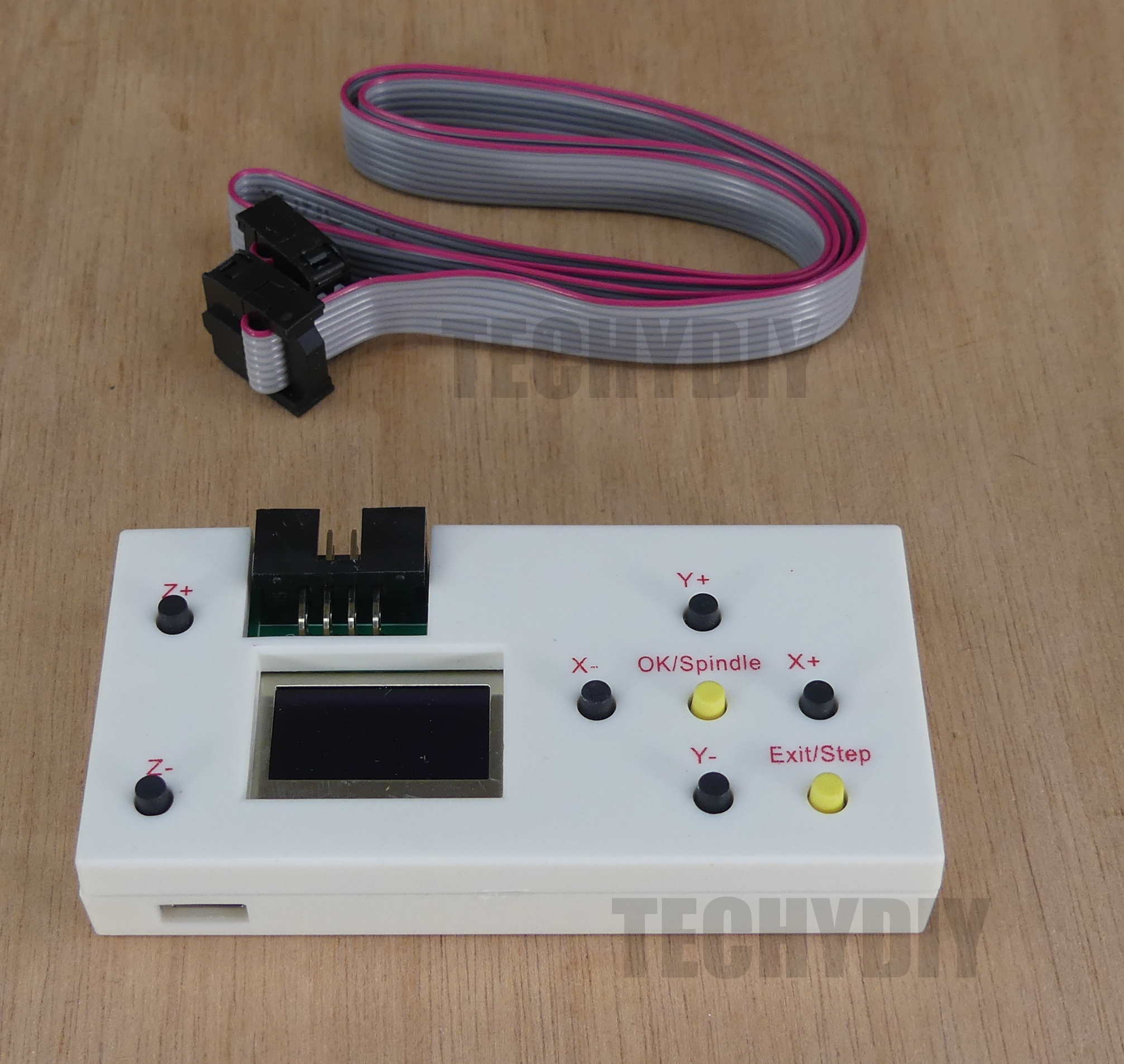
And a standalone controller which allows the machine to be operated without a computer
The gantry is constructed from 2040 aluminium extrusion and 10mm thick aluminium side plates
The Z axis runs on 10mm diameter rods and linear bearings
And the X axis runs on 15mm linear rails
The base is constructed form 4040 aluminium extrusion and 10mm thick aluminium plates
There is an 8mm thick aluminium table bed
Which measures 300 x 200mm
And it has m6 threaded holes
for use with the included work holding clamps
The y axis runs on 12mm diameter rods and linear bearings
And all of the axes are driven by nema 17 stepper motors
and 8mm leadscrews.
The working area of the machine is 280 X 192mm
with a maximum z axis travel of 68mm
and 75mm clearance height
I have dismantled the controller and this is the pcb
On the top left is the power switch
The microcontroller is an ATMEGA328P Running GRBL version 1.1H
Grbl is open source software that interprets gcode commands and controls stepper and spindle motors.
There are four connectors for stepper motors, two are Y axis outputs, one of which is unused
There are also connectors for the emergency stop switch, 48v dc power supply, the spindle motor and a three pin laser connector
The A4988 stepper motor drivers are hidden under the heatsink
Driver current can be adjusted with the potentiometers
The usb serial port connection is provided by a CH340G usb to serial port chip with a micro usb connector
On the bottom of the pcb there are connectors for the limit switches and the probe
None of these appear to be connected through opto-couplers, which can help with noise immunity
On the right there is a reset switch
A pwm or pulse with modulation signal from the microcontroller switches a mosfet and this controls the spindle motor speed.
There are single limit switches for the x and y axes
And two for the z axis.
A single switch on each axis is sufficient for homing and soft limits, but not to fully implement hard limits.
The power supply is a chassis unit with a plastic cover over the electrical connections.
I checked that the power supply chassis was earthed
and I also measured the voltage between the output wires and earth.
These measured about 200mVolts which indicates that the output is not mains referenced, which is good.
The machine comes with a good instruction manual
Tools
and a usb stick with software, drivers, examples and pdfs
Now lets assemble the machine
First we install eight spring loaded t nuts into each side of the base frame
They are spaced 20mm apart and 23 mm from the end of the frame
I cut a tool to make spacing the nuts easier but you can just use a ruler
The same for the other side
Next the gantry is offered up to the base frame
And it is attached with m5 16mm bolts
Check that the spacing between the gantry and the base is 13mm
and then tighten all the bolts
The same on the other side
That’s the frame assembled
Next, we are going to fit the limit switches
To make assembly easier, I ran the screws in and out a few times to clear the threads
Then the switches are attached to the brackets
Next, we are going to fit bolts and t nuts to the controller
It’s easier to plug the stepper motor cables into the controller before mounting it.
The t nuts are horizontally aligned
Then they are Inserted into the slots and gently tightened.
Be careful because if the screws are over tightened, its really easy to crack the acrylic.
Next, the emergency stop switch is fitted
The spindle motor is installed
An extension lead is connected to the spindle motor lead
and its then connected to the spindle motor terminals on the controller pcb
The final part of the assembly was cable management.
There were no specific instructions for this
I kept the stepper motor and spindle motor cable separate from the limit switch cables to avoid any interference
And I used some stick on cable tie clips to attach the cables to the frame.
The offline controller can be used to operate the machine without a computer
Its ribbon cable is plugged into the port on the control pcb and the offline controller
Check that the emergency stop switch is not activated
And the power is switched on
The offline controller has an SD memory card slot
And a micro sd card and sd adapter are also supplied
To run gcode files they are first transferred onto this memory card
Scroll through the menu with the y keys and select CONTROL with ok
The x, y and Z axes can be jogged
and the step size changed by pressing the step key
The spindle can be turned on and off with the spindle key
Pressing and holding exit returns to the main menu
I have clamped some mdf to the table bed
And I am going to use one of the v bits supplied with the machine
The v bit is installed into the er11 collet and tightened
The axes are jogged to where I want to start the job
And the bit is jogged using the paper to indicate when its just touching the surface
We select the file menu
And choose one of the gcode examples that Sainsmart have preloaded on the SD card
The Software for windows is provided on a usb stick
This includes a usb driver and an opensource application called Candle.
First the usb driver is installed
And then the grblcontrolcandle folder is copied onto the computer
Double clicking on the grblcontrol candle.exe file starts the application
Remove the offline controller cable
Check that the emergency stop switch isnt activated
Plug in the usb cable
And turn on the power
Select the com port
The machine starts in a locked state to remind us to home the machine
If we don’t want to home straightaway we can unlock first and then home later
or we can just home straight from the locked state
By default the homing cycle sets the machine origin or zero point to the top right hand corner and it will be operating in negative space
The axes can be jogged
And we can set the step size
To view the grbl configuration type $$ into the console
Before making any changes its a good idea to take a copy
This can be pasted into a notepad document
The grbl configuration guide can be found on github
If the axes are moving in the wrong directions, then that can be changed with the $3 direction port invert setting
For this machine $3 should have a value of 2, which means that the x and z axes directions are normal and the Y axis direction is reversed
Next the maximum travel settings are configured for the x,y and z axes
I measured these as 280, 192 and 68 mm respectively
$13=0 sets the machine to report in mm
$20=1 enables soft limits
Soft limits is a safety feature that helps to prevent the axes move beyond their limits and crashing into something.
I will give a quick demo of soft limits working
I can jog the y axis once
but if I try it again nothing happens
This is because the travel would exceed 192 which is the value of the y axis maximum travel setting
If I change the step size to 10 then I can jog until the limit is exceeded
If you execute gcode and it exceed the limits then it will issue a feed hold and set a system alarm.
This is quite a useful feature but it can also be a bit confusing at times when the machine refuses to move.
The spindle can be manually turned on and off
I measured the maximum spindle speed as just under 12000 rpm
and the minimum at approximately 8000 rpm
Entering $30=12000 sets the maximum spindle speed in grbl
and $31=8000 sets the minimum spindle speed
We can also change the Candle maximum and minimum spindle speeds under service, settings
I have set the stepper motors to be always enabled with $1=255
Finally I tested the stepper motors
and set the maximum rates for all three axes to 2500
and the acceleration to 400
These might be a little bit too ambitious but we will soon find out.
A spoilboard is a great way of avoiding damage to the table bed
I have created a design in carbidecreate
and exported the gcode
The machine is homed
A 3.175mm two flute bit is inserted into the er11 collet
And the collet tightened
The axes jogged to the bottom left hand corner
The board is secured to the table bed with painters tape and mitre adhesive
And then the bit is jogged down until it just pinches the paper
The z axis is zeroed
The bit jogged into the corner
And the xy axes zeroed
The gcode file is opened and sent to the machine by pressing send
The pause button is pressed to continue
With the holes cut, the board is secured to the table bed with m6 countersunk screws
To flatten the spoilboard I am using a 22mm bottom clearing bit
which has a 6mm shaft, so I need to change the er11 collet to 6mm
It’s worth buying a set of these.
Next, I am going to make a pcb
The pcb design was created in Eagle
I had already run some test patterns on scrap pcb board
and the smallest usable track width was about 0.25mm wide which is about 10mils
So I used 20 mil traces widths which are 0.508mm wide
The gerber and drill files were exported
These files were loaded into flatcam
and it was then used create the gcode files
The parameters that I used for the bottom layer were a tool diameter of 0.1mm,
cut depth of 0.05mm,
feed rate 100mm/min and depth per pass of 0.01mm
The copper layer of a pcb is very thin and the board is not flat.
To mill the fine traces on the board we are going to use a v bit.
The deeper that we cut with the v bit, the wider the cut width, so if we are not careful we can end up with variable widths.
One way around that is to use an electrical probe to map the height of the board in a matrix pattern and then modify the gcode to take account of the different heights.
We can do that from candle, using the probe input on the machines controller pcb.
It’s not a great idea to connect a probe lead directly to the probe input, as its probably directly connected to the microcontroller and it will have a high impedance input., which can lead to false triggering by noise.
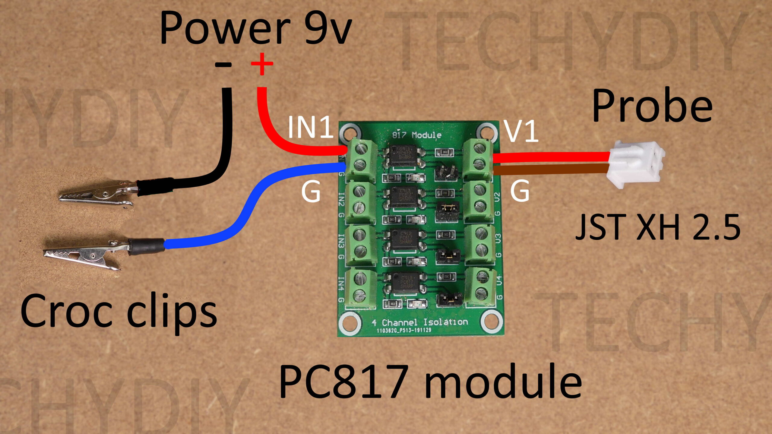
What I did was to use an optocoupler module to isolate the probe, it can be powered by an independent 12volt power supply or 9v battery.
A couple of croc clips are used to connect to the v bit and the board
and a jst xh 2.5mm connector is used to connect to the probe input on the controller pcb.
If you dont have a crimp tool then you can buy the connectors with pre-terminated tails.
The gcode for the bottom layer was loaded into candle
The pcb was attached to the spoilboard with painters tape and mitre adhesive
The bit jogged to the bottom left hand corner
And the xy position zeroed
The probe croc clips were connected to the board and the v bit
And then I am going to use candles default probe script to find the surface of the pcb material
Now the z axis can be zeroed
and the z axis jogged up to break the electrical connection
Next we are going to create a height map
The size of the outline is selected with auto
The size of the grid is entered
zt specifies the probe starting height
and zb is the maximum distance the probe will travel
Selecting probe starts the mapping process
It is a pretty slow process
Then we can remove the croc clips
Select the edit mode button and then select the Use height map check box
And we can send the gcode to the machine
The v bit is changed to an 0.3mm diameter drill bit
The z axis zeroed
The pcb drill gcode opened
And sent to the machine.
If you have ever tried to drill pcb holes by hand you will appreciate just how magic this is.
Next, the drill bit was swapped for an 0.8mm corn bit.
Again the z axis was zeroed
The outline gcode loaded and sent to the machine
Next, I tried cutting some half millimetre thick copper sheet in a Celtic knot pattern.
To avoid using tabs I used painters tape and mitre adhesive to hold down the copper and I also added some screws.
The copper was very uneven so I used a height map.
I also attached some dpc material to the table bed with double sided adhesive tape to act as a dust shield
Next, up was aluminium
To provide extra cooling, I strapped an air nozzle to the spindle holder
and connected it to a compressor
I ran quite a few tests with an adapative tool path and the best result was with quite conservative settings
So to try that out I created a design in fusion
with an adaptive and a contour path
I tested it on some mdf
Then on aluminium
First the adaptive path
Aluminium started to stick to the end mill
Then the contour pass
This started to gum up, the aluminium became quite hot and it started sticking to everything
So I added some cutting fluid to increase the cooling.
I didn’t use any finishing passes so I think it was a reasonable result.
I ran some more tests to see if I could use a larger maximum step down in the adaptive path
I found that the spindle couldn’t maintain its speed under load at much less than 10000 RPM
And pretty much no matter what I did the single flute end mills were coated in aluminium
So finally I tried a two flute end mill, lowered the optimal load and the step down
This was about as good as it got and the end mill was clean.
Ok, so the 3020 Pro Max has some significant improvements over a 3018 type machine
If we compare it with the 3018 prover
The Pro max has a thicker frame
Larger diameter linear rods
and 15mm linear rails instead of 10mm linear rods
The pro max is obviously stiffer
It also has a more powerful 300w spindle motor which can operate at 12000rpm,
more powerful stepper motors and parts made from aluminium instead of plastic.
The increased z axis height means that you can work on thicker materials
The 3020 Pro max lacks a full set of limit switches, but you can still use homing and soft limits
Overall, its a fun little machine, a good upgrade over a 3018 and a good option for the hobbyist making small parts from wood, plastics and occasionally soft metal.
Thanks for watching,
see u again next time
Nice
Hi
Thanks for making the review video’s of the hobby CNC machines, they really give a better insight in the possibilities of the machines. Could you give a small word of advice? I would like to start to learn working with a CNC and my primary hobby projects would be milling aluminum for small interface parts, carving PCB’s and some wood work. A working area of 300x200x72mm is sufficient. Potential future upgrade with 4th axis, laser or 3D printing would be really interesting but is not a ‘must-have’ right now and might make the choice just overly complicated…
I checked your videos of the Genmitsu 3020-PRO MAX and Genmitsu PROVerXL 4030. The PROVerXL 4030 might give more potential for bigger parts, but I really want to mill aluminum from time to time. Do you believe the 3020-PRO MAX would be the better choice or is there another device I should look at?
Kind Regards
Hello
Would this CNC be useful if the main work is machining aluminum? I would like to achieve ±0.1 and max ±0.2mm tolerances and dimensions of the 3020 would be sufficient. Would the PROVerXL 4030 be a better choice or another CNC in one of your reviews for the same budget range as a PROVerXL 4030?
Many thanks in advance. Your videos clear up a lot of things on the machines.
Best Regards
Jef
You can mill aluminium with the 3020 but its not a stiff machine, so the depth of cut and feed rate have to be relatively low. It is quite a bit stiffer than a typical 3018 type machine though.
The PRoverxl is considerably larger (takes up a lot of space) and the frame is stiffer, but it uses rollers. On balance I would say the Proverxl is the better option but consider the space required.
The other option is to look for generic 3020 or 6040 Chinese cnc machines, these usually come with mach3 controllers, which I wouldn’t recommend if you want to do any pcb milling, as height mapping (essential for pcb milling) can be an issue.
At this price range everything is a bit of a compromise.
I your video about the genmitsu 3020 max pro is superb loved it
could you give me spoilboard GCODE for make one please.
I’m new to cnc
Hello techy, could you show me how to make spoilboard for Genmitsu 3020-Pro Max or can you give me the GCODE any help would be appreciated thank you.