
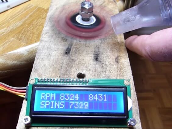
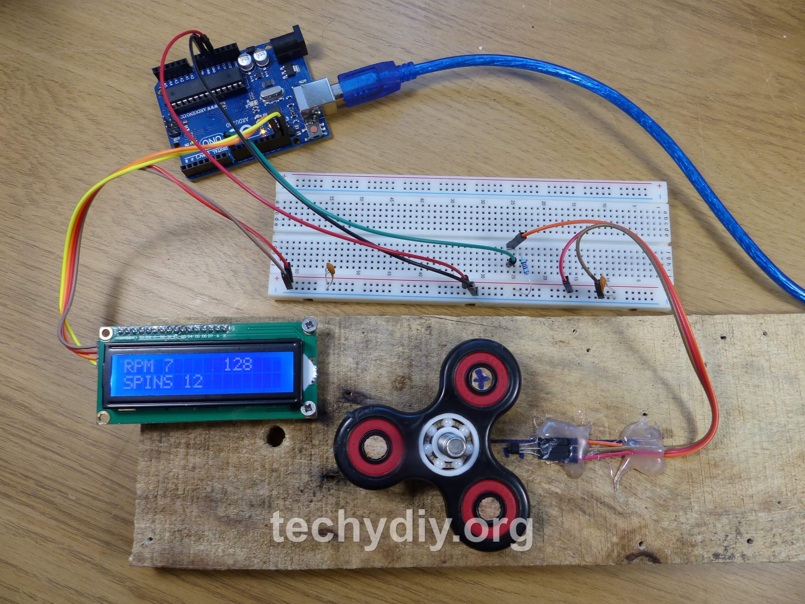
This was a fun experiment measuring the rotational speed (rpm) of a fidget spinner using an Arduino Uno, a hall effect sensor and a neodymium magnet. Then seeing just how fast I could make the spinner spin with a shop vac!
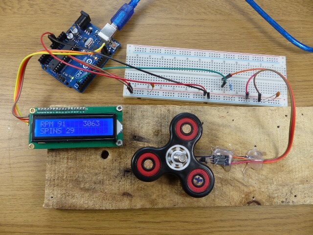
Measuring Spinner RPM every Revolution with a Hall Effect Sensor and Neodymium Magnet
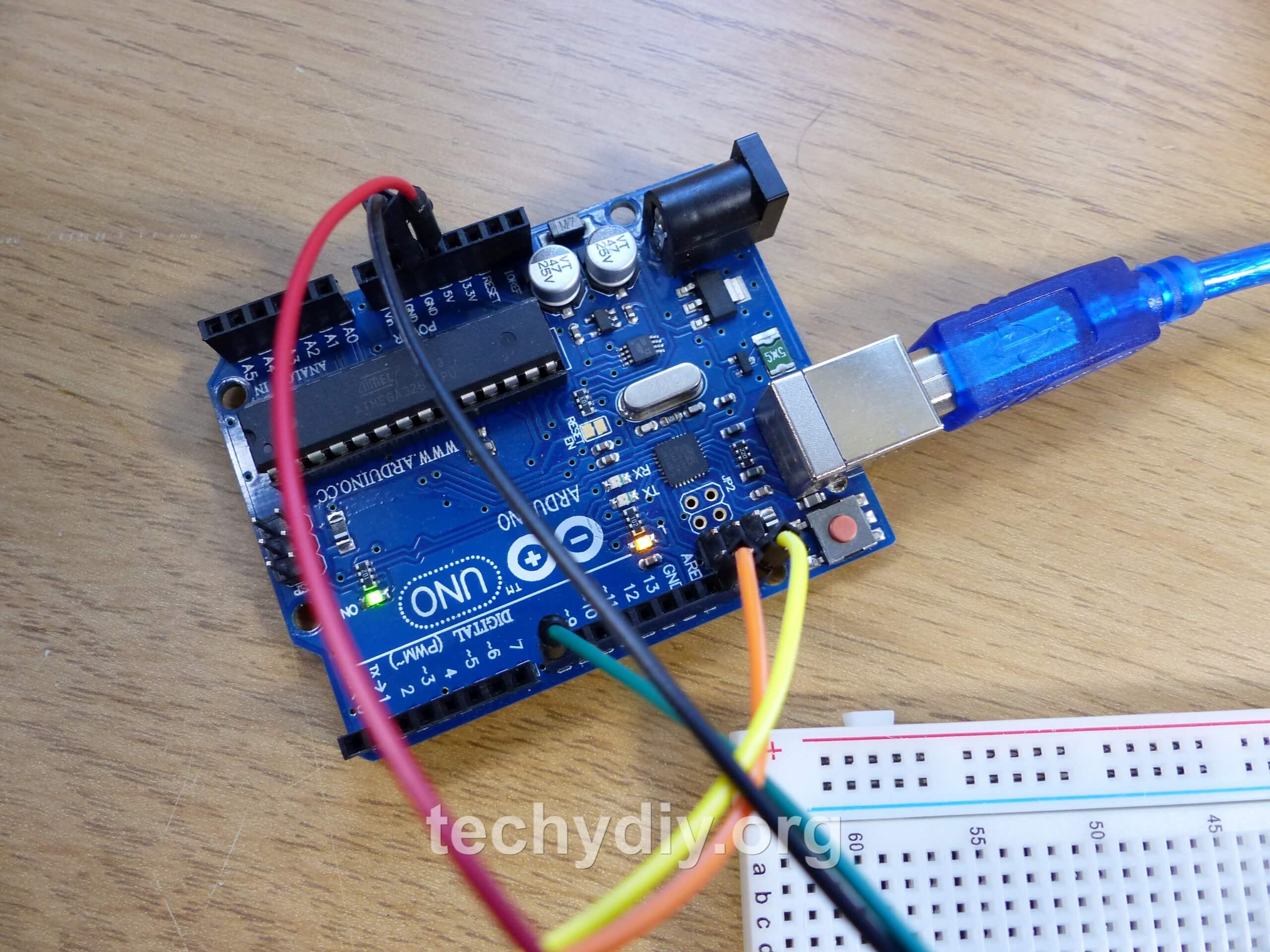
The Hall effect sensor output was connected to the Arduino Uno digital input pin 2. The neodymium magnet was glued to a section of 8mm wooden dowel and pushed into one of the outer bearings on the fidget spinner.
// Fidget spinner RPM counter
// techydiy.org
// https://creativecommons.org/licenses/by-nc-sa/4.0/

// Calculates and displays the RPM of a fidget spinner for every revolution
// Hall effect sensor connected to digital pin 2

// Uses the lcd ibrary from F Malpartida
// https://bitbucket.org/fmalpartida/new-liquidcrystal/wiki/Home

#include <Wire.h>
#include <LiquidCrystal_I2C.h>

LiquidCrystal_I2C lcd(0x27, 2, 1, 0, 4 ,5, 6, 7, 3, POSITIVE);

const byte ledpin = 13;     //  Led output
const byte interruptPin = 2;  //  Hall effect sensor connected to this pin
volatile unsigned int spins =0;   // Total spins
volatile unsigned long  timenow=0;   //
volatile unsigned long  lasttime=0;   // Last time in millis interupt routine was called
volatile unsigned int rpm=0;           // Current rpm
unsigned int displayrpm=10;  // Displayed rpm
unsigned int displayspins = 999; // Displayed spins
volatile unsigned int maxrpm=0;       // Maximum rpm

void setup()
{
  lcd.begin(16,2);
  lcd.clear();

  pinMode(ledpin, OUTPUT);  // Onboard LED output
  pinMode(interruptPin, INPUT_PULLUP);
  attachInterrupt(digitalPinToInterrupt(interruptPin), countspin, RISING); // Digital pin 2 hardware interrupt

}

void loop() {

  if (rpm != displayrpm | spins != displayspins) {    // Only update the display if the RPM or spins change

    displayrpm = rpm;         // Update rpm displayed
    displayspins = spins;     // Update spins displayed

    lcd.setCursor(0,0);
    lcd.print("RPM ");
    lcd.setCursor(4,0);
    lcd.print(rpm, DEC);       // Print the RPM on the lcd display
    lcd.print("     ");

    lcd.setCursor(10,0);
    lcd.print(maxrpm, DEC);     // Print the Max RPM on the lcd display

    lcd.setCursor(0,1);
    lcd.print("SPINS ");        // Print the no. of spin on the lcd display
    lcd.print(spins);
    lcd.print("     ");

  }
}


// Interupt service routine for digital pin 2
// connected to the hall effect sensor
void countspin()
{
  digitalWrite(ledpin, !digitalRead(ledpin)); // Toggle LED

  spins++;              // Increment spins counter
  timenow=micros();     // Read current time

  rpm = 60000000  / ( timenow - lasttime ) ;    // Calculate RPM
  lasttime=timenow;                          // Store current time

  if(rpm > maxrpm){     // Update max rpm if it has increased
    maxrpm=rpm;
  }

}
3144 Hall effect switch datasheet
Measuring the Spinner RPM once every second
The following sketch uses a timer 1 interrupt and a hardware interrupt to measure the RPM over a one second period.
// Fidget spinner RPM ccunter
// techydiy.org
// https://creativecommons.org/licenses/by-nc-sa/4.0/

// Measures RPM over a 1 second period
// with a minimum resolution of 60 rpm
// Increase the period to increase the resolution

// Uses the lcd ibrary from F Malpartida
// https://bitbucket.org/fmalpartida/new-liquidcrystal/wiki/Home
//
// and the Timer1 library
// https://playground.arduino.cc/Code/Timer1

#include <TimerOne.h>
#include <Wire.h>
#include <LiquidCrystal_I2C.h>

LiquidCrystal_I2C lcd(0x27, 2, 1, 0, 4 ,5, 6, 7, 3, POSITIVE);

const byte ledpin = 13;              // Onboard Led
const byte interruptPin = 2;         // Hall effect sensor connected to this pin
volatile unsigned int spins =0;      // Number of spins counter
volatile unsigned int rpm=0;         // The current RPM value
volatile unsigned int maxrpm=0;      // The maximum RPM value
unsigned int displayrpm=9999;        // The currently displayed RPM value

void setup()
{
  lcd.begin(16,2);   // Initialise lcd display
  lcd.clear();       // Clear lcd display

  pinMode(ledpin, OUTPUT);  // Onboard LED output

  Timer1.initialize(1000000); // set a timer of length 1000000 microseconds (or 1 second )
  Timer1.attachInterrupt( timerIsr ); // attach the service routine

  pinMode(interruptPin, INPUT_PULLUP);
  attachInterrupt(digitalPinToInterrupt(interruptPin), countspin, RISING); // Digital pin 2 hardware interrupt

}

void loop()
{
   if (rpm != displayrpm) {  // Only update if the RPM value has changed

      lcd.setCursor(0,0);
      lcd.print("RPM ");
      lcd.print(rpm, DEC);   //  Display RPM
      lcd.print("     ");;
      lcd.setCursor(0,2);
      lcd.print("MAX ");
      lcd.print(maxrpm, DEC);    // Display maximum RPM achieved

   }
}


// Timer Interupt
// Called every one second
// Calculates rpm and updates maximum rpm

void timerIsr()
{
  rpm = spins * 60 ;  // Calculate RPM
  spins = 0;           // Reset spin counter

  if(rpm > maxrpm){    // Update maximum RPM
    maxrpm=rpm;
  }
}

// Hardware interupt for digitsl input 2
// which is connected to the hall effect sensor.
// When the input transitions from low to high
// it increments the spins counter and toggles the led.

void countspin()
{
  digitalWrite(ledpin, !digitalRead(ledpin)); // Toggle LED
  spins++;                            // Increment spins counter
}
How fast can the spinner spin with a shop vac?
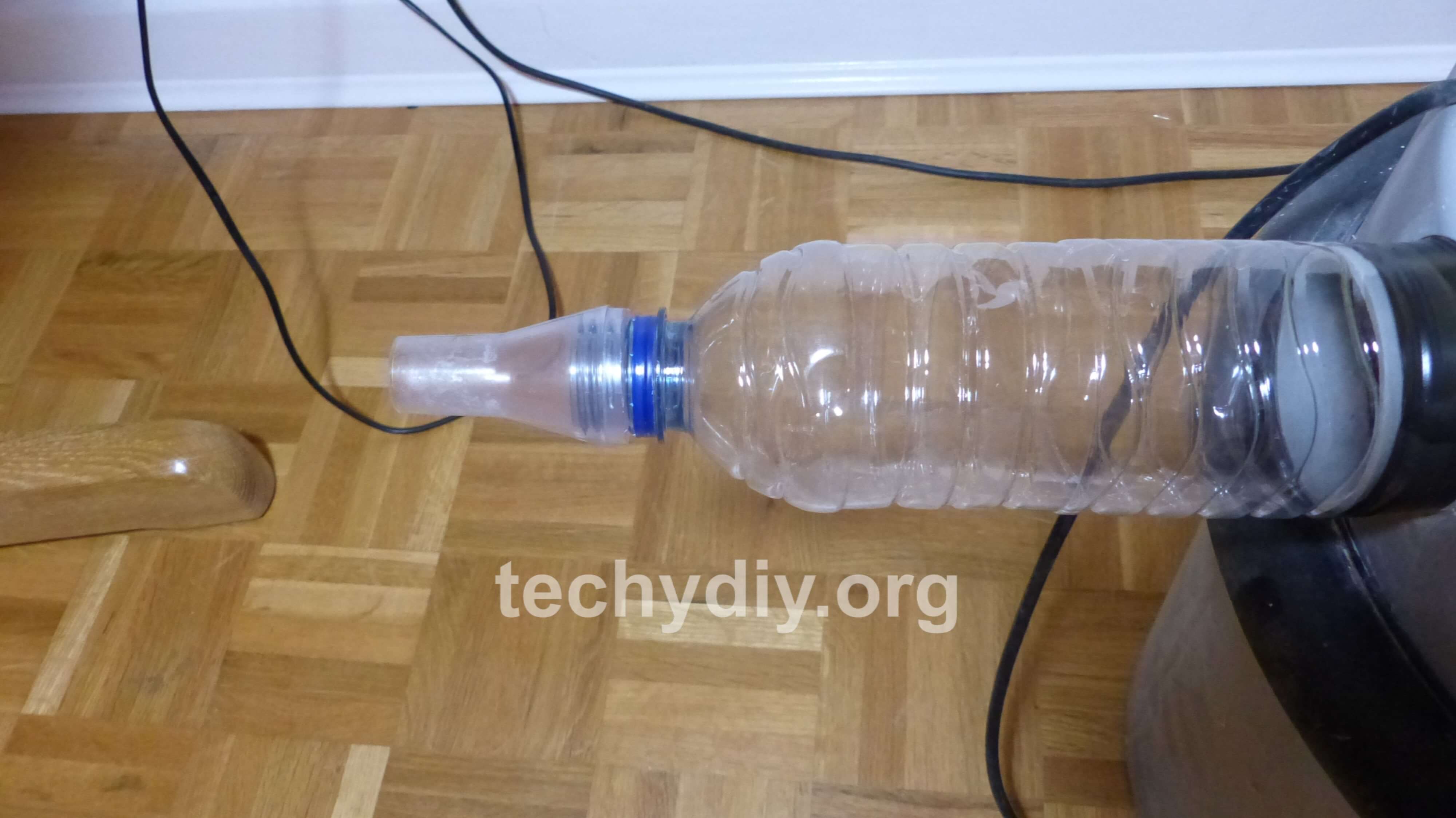
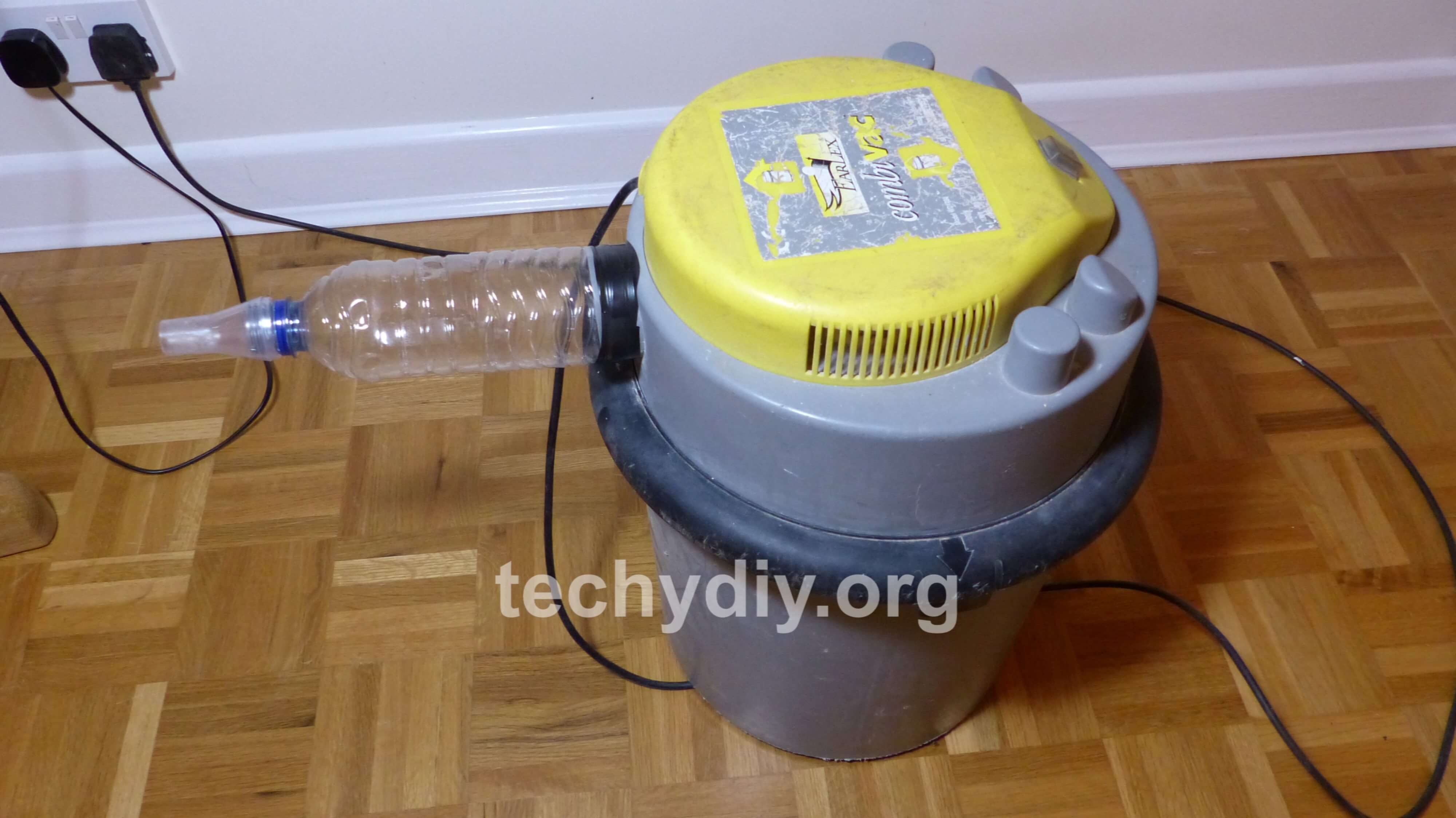
To test the Arduino tachometer at higher rpm values, I used a shop vac. The bottom of a drinks bottle was cut off and then the bottle inserted into the shop vac blower output. I also added a small nozzle to increase the air speed.
Measuring the Spinner RPM with the timer input capture unit
It is also possible to make the Arduino timer do most of the work.
The hall effect sensor is connected to pin 8.
The timer counts the prescaled clock and then stores the count when the magnet passes over the hall effect sensor. An interrupt is generated and this then retrieves the stored count and uses it calculate the rpm value.
The prescaler is used to reduce the clock frequency.
// Fidget spinner RPM counter
// techydiy.org
// https://creativecommons.org/licenses/by-nc-sa/4.0/


// Calculates and displays the RPM of a fidget spinner for every revolution
// Hall effect sensor connected to ICP1 digital pin 8
// Using timer input capture unit


// Uses the lcd ibrary from F Malpartida
// https://bitbucket.org/fmalpartida/new-liquidcrystal/wiki/Home
//

#include <Wire.h>
#include <LiquidCrystal_I2C.h>

LiquidCrystal_I2C lcd(0x27, 2, 1, 0, 4 ,5, 6, 7, 3, POSITIVE);

const byte ledpin = 13;     //  Led output
const byte interruptPin = 8;  //  Hall effect sensor connected to this pin
volatile unsigned int spins =0;   // Total spins
volatile unsigned int rpm=0;           // Current rpm
unsigned int displayrpm=10;  // Displayed rpm
unsigned int displayspins = 999; // Displayed spins
volatile unsigned int maxrpm=0;       // Maximum rpm
volatile byte countoverflow=0;       // counter overflows

void setup()
{
  lcd.begin(16,2);
  lcd.clear();

  pinMode(ledpin, OUTPUT);  // Onboard LED output
  pinMode(interruptPin, INPUT_PULLUP);   //   Hall effect sensor connected to this pin

  noInterrupts();
  TCCR1A = 0;    // Normal wave generation mode
  TCCR1B = bit(ICNC1) | bit(ICES1) | bit(CS12) | bit(CS10);  // Timer counter contol register
                                                // Noise canceller, Edge detect
                                                //  /1024 prescale clock frequency

  // TCCR1B = bit(ICES1) | bit(CS12) | bit(CS10);  // Noise canceller off instead


  TIMSK1 = bit(ICIE1) | bit(TOIE1);       // Timer interrupt mask register
                                          // Input capture interrupt enable,  Timer overflow interrupt enable

  interrupts();
}

void loop() {

  if (rpm != displayrpm | spins != displayspins) {    // Only update the display if the RPM or spins change

    displayrpm = rpm;         // Update rpm displayed
    displayspins = spins;     // Update spins displayed

    lcd.setCursor(0,0);
    lcd.print("RPM ");
    lcd.setCursor(4,0);
    lcd.print(rpm, DEC);       // Print the RPM on the lcd display
    lcd.print("     ");

    lcd.setCursor(10,0);
    lcd.print(maxrpm, DEC);     // Print the Max RPM on the lcd display

    lcd.setCursor(0,1);
    lcd.print("SPINS ");        // Print the no. of spin on the lcd display
    lcd.print(spins);
    lcd.print("     ");

  }
}

// Input capture interrupt routine
ISR(TIMER1_CAPT_vect){

    TCNT1 = 0;              // Reset counter to zero
    rpm = 60000000 / (( ICR1 + countoverflow * 65535 ) * 64 );    // Total count
    countoverflow = 0;

   // digitalWrite(ledpin, !digitalRead(ledpin)); // Toggle LED
    spins++;              // Increment spins counter

    if(rpm > maxrpm){     // Update max rpm if it has increased
      maxrpm=rpm;
    }
}


// Counter overflow interrupt routine
ISR(TIMER1_OVF_vect){
    TCNT1 = 0;            // Reset counter to zero
    countoverflow++;      // Increment the counter over flows
    digitalWrite(ledpin, !digitalRead(ledpin)); // Toggle LED

}
Measuring Spinner RPM with a Light Dependent Resistor (LDR)
Measuring the spinner speed is also possible using a light source along with a photo transistor or a light dependent resistor (LDR) as a receiver.
The fidget spinner breaks the light beam and the Arduino measures the resulting pulse.
In this case I have used an LDR and a 1K resistor connected as a potential divider, with the output connected to pin 8.
The sketch takes account of the number of arms on the fidget spinner and once again uses the input capture interrupt.
// Fidget spinner RPM counter
// techydiy.org
// https://creativecommons.org/licenses/by-nc-sa/4.0/


// Calculates and displays the RPM of a fidget spinner for every part revolution
// Light dependent resistor (LDR)  connected to ICP1 digital pin 8
// Using timer input capture unit


// Uses the lcd ibrary from F Malpartida
// https://bitbucket.org/fmalpartida/new-liquidcrystal/wiki/Home
//

#include <Wire.h>
#include <LiquidCrystal_I2C.h>

LiquidCrystal_I2C lcd(0x27, 2, 1, 0, 4 ,5, 6, 7, 3, POSITIVE);

const byte spinnerarms = 3;   // The number of arms on the spinner
const byte ledpin = 13;     //  Led output
const byte interruptPin = 8;  //  LDR connected to this pin
volatile unsigned int spins =0;   // Total spins
volatile unsigned int rpm=0;           // Current rpm
unsigned int displayrpm=10;  // Displayed rpm
unsigned int displayspins = 999; // Displayed spins
volatile unsigned int maxrpm=0;       // Maximum rpm
volatile byte countoverflow=0;       // counter overflows

void setup()
{
  lcd.begin(16,2);
  lcd.clear();

  pinMode(ledpin, OUTPUT);  // Onboard LED output
  pinMode(interruptPin, INPUT_PULLUP);   //   Hall effect sensor connected to this pin

  noInterrupts();   // Turn off interrupts
  TCCR1A = 0;    // Timer counter contol register. Normal wave generation mode
  TCCR1B = bit(ICNC1) | bit(ICES1) | bit(CS12) | bit(CS10);  // Timer counter contol register
                                                // Noise canceller, Edge detect
                                                //  /1024 prescale clock frequency

  // TCCR1B = bit(ICES1) | bit(CS12) | bit(CS10);  // Noise canceller off instead


  TIMSK1 = bit(ICIE1) | bit(TOIE1);       // Timer interrupt mask register
                                          // Input capture interrupt enable,  Timer overflow interrupt enable

  interrupts();   // Turn interrupts on
}

void loop() {

  if (rpm != displayrpm | spins != displayspins) {    // Only update the display if the RPM or spins change

    displayrpm = rpm;         // Update rpm displayed
    displayspins = spins;     // Update spins displayed

    lcd.setCursor(0,0);
    lcd.print("RPM ");
    lcd.setCursor(4,0);
    lcd.print(rpm, DEC);       // Print the RPM on the lcd display
    lcd.print("     ");

    lcd.setCursor(10,0);
    lcd.print(maxrpm, DEC);     // Print the Max RPM on the lcd display

    lcd.setCursor(0,1);
    lcd.print("SPINS ");        // Print the no. of spin on the lcd display
    lcd.print(spins / spinnerarms );   // Adjust for part spins
    lcd.print("     ");

  }
}

// Input capture interrupt routine
ISR(TIMER1_CAPT_vect){

    TCNT1 = 0;              // Reset counter to zero
    rpm = 60000000 / (( ICR1 + countoverflow * 65535 ) * 64 * spinnerarms);   // Calculate RPM
    countoverflow = 0;

    digitalWrite(ledpin, !digitalRead(ledpin)); // Toggle LED
    spins++;              // Increment spins counter

    if(rpm > maxrpm){     // Update max rpm if it has increased
      maxrpm=rpm;
    }
}


// Counter overflow interrupt routine
ISR(TIMER1_OVF_vect){
    TCNT1 = 0;            // Reset counter to zero
    countoverflow++;      // Increment the counter over flows
}