
In this article, I am going to describe how I made an LED infinity illusion mirror, using an Ikea mirror tile, a sheet of glass, some reflective window film, a reel of led strip light tape and some wood.
Parts:
US: Silver reflective window film:
UK: Silver reflective window film
US: 12v White LED strip
UK: 12v White LED strip
US: Speaker wire
UK: Speaker wire 2×13/0.2mm
US: DC power adapter 5.5mm 2.1mm
UK: DC power adapter 5.5mm 2.1mm
US: 12v DC Power supply
UK: 12v DC Power supply
Matt black spray paint
UK: Matt black spray paint
US: Rustoleum Silver Furniture paint
UK: Rustoleum Silver Furniture paint
US: Rustoleum graphite chalky finish paint
UK: Rustoleum graphite chalky finish paint
US: Rustoleum furniture lacquer
UK: Rustoleum furniture lacquer
Ikea LOTS mirror tiles:
US: http://bit.ly/2hISUQW
UK: http://bit.ly/2i2y9NY
UK Glass sheet: 30cm x 30cm x 4mm (this should be the same size as the mirror tile)
US Glass sheet 12″ x 12″ x 1/8″
UK Wood sides 20 x 70 x 2400 mm: http://bit.ly/2igZbAC
US Wood sides 1″ x 3″ x 8′ ( 3/4″ x 2-1/2″ finished size)
Plywood back: 30cm x 30cm (12″ x 12″ ) (this should be the same size as the mirror tile)
US: Wooden dowels 1/4″
UK: Wooden dowels 6mm
Tools:
Router table:
US: http://amzn.to/2iiBgRg
UK: http://amzn.to/2hWqd18
Mitre saw:
US: http://amzn.to/2hurtrh
UK: http://amzn.to/2i4JuNq
4mm straight router cutter bit:
US: http://amzn.to/2hKlqBC
UK: http://amzn.to/2hcR4r1
16mm straight router cutter bit:
US: http://amzn.to/2hKf2ul
UK: http://amzn.to/2i4EiJy
Soldering iron:
US: http://amzn.to/2i4ylMH
UK: http://amzn.to/2hYvirW
Helping hand:
US: http://amzn.to/2hKkDAM
UK: http://amzn.to/2hYpjDN
Hot glue gun:
US: http://amzn.to/2hcVdv7
UK: http://amzn.to/2hcWYIv
Drill:
US: http://amzn.to/2iewjwX
UK: http://amzn.to/2h579f0
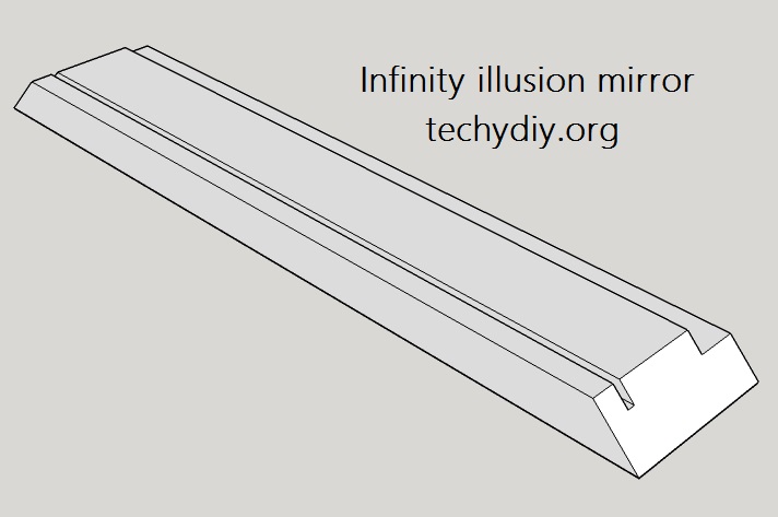
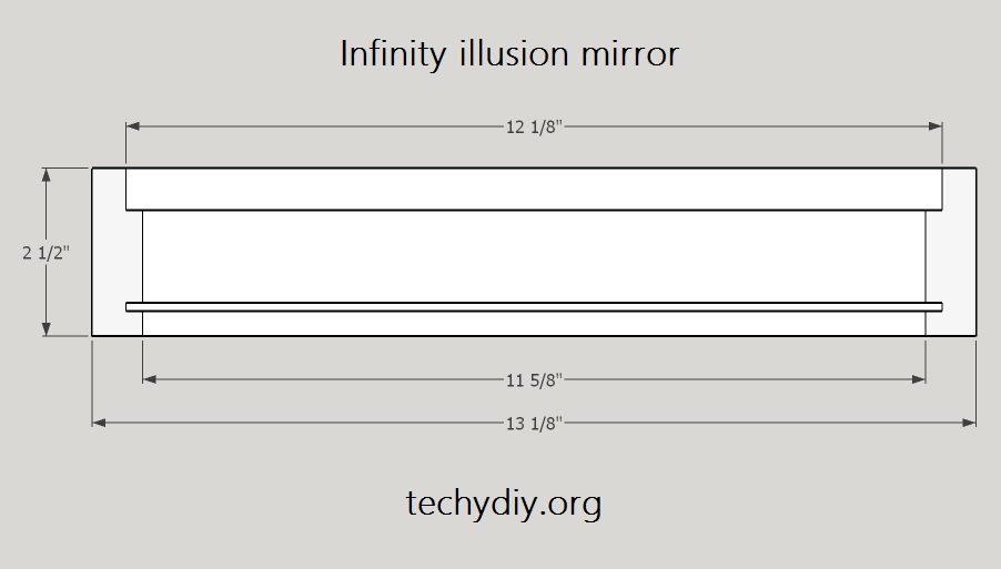
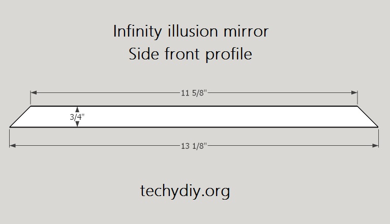
FRAME PROFILE
Frame profile with imperial measurements
These measurements are for use with:
- 3″ x 1″ wood ( finished size 3/4″ x 2-1/2″ )
- 12″ x 12″ x 1/8″ mirror & glass
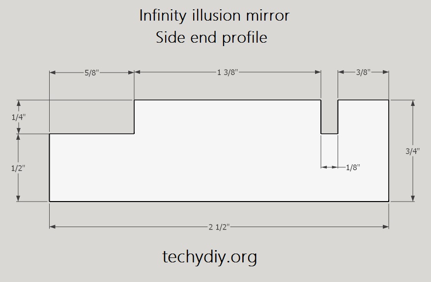
Cut a groove in the wood on the router table using a 1/8″ straight bit
Cut a rabbet in the wood using a 5/8″ straight bit
Frame profile with metric measurements
Cut a groove in the wood on the router table using a 4mm straight bit
Cut a rabbet in the wood using a 16mm straight bit
FRAME MITRES
Cut the wood into 4 pieces
set the Mitre saw to 45 degrees
Use a sacrificial fence on the mitre saw
Cut right-hand side mitres on all four pieces of wood
Insert the glass into the groove on one of the pieces and mark the correct width for the side.
Using the sacrificial fence, line up the mark on the piece of wood and then clamp one of the offcuts onto the fence as a stop block.
Cut the first piece of wood to size and remove it from the saw
Place each of the remaining three wood pieces against the stop block and cut them to size.
Dry fit the sides and the glass to check it all fits
SPRAY PAINT THE INSIDES BLACK
Mask and spray the insides of the wood pieces with matt black paint
ASSEMBLE AND GLUE THREE SIDES
Apply wood glue to one side
Assemble the sides
Clamp together with a band clamp
Leave to dry
CORNER DOWELS
To strengthen the glued corners, install wooden dowels through them.
Clamp the Corner dowel drilling jig to one of the corners
Clamp a wood block to the other side
Drill two holes through the corner
Repeat this for the other glued corner
Apply wood glue to the dowels
Tap the dowels through the holes with a mallet
Once the glue is dry cut off the excess dowels
Sand the dowels flat
INSTALL THE LED STRIP ONTO THE FRAME
The next job was to install the led strip onto the frame. Now I could have wrapped the tape around the inside in one piece, but I thought it would look more uniform If I cut it into four sections and then soldered them together again with flexible wires.
I CUT THREE LENGTHS OF LED TAPE TO LENGTH AT THE MARKED POSITIONS.
TINNED THE CONNECTIONS ON EACH TAPE AND ALSO THE STRIPPED WIRES.
SOLDERED THE WIRES TO THE TAPES.
MARKED A PENCIL LINE ALONG THE CENTRE OF THE WOOD PIECE.
REMOVED THE BACKING FROM THE FIRST LENGTH OF LED TAPE
POSITIONED IT ON THE SIDE USING THE PENCIL LINE AND STUCK IT DOWN
I THEN REPEATED THE PROCESS FOR THE OTHER TWO LENGTHS OF LED TAPE, MAKING SURE THAT THEY WERE ORIENTATED IN THE SAME DIRECTION
THE WIRES WERE THEN CUT TO LENGTH AND SOLDERED TO THE NEIGHBORING LED TAPE, CONNECTING POSITIVE TO POSITIVE AND NEGATIVE TO NEGATIVE.
THE LED STRIP was then tested.
CREATE A ROUTE FOR THE LED POWER CABLE
I realised that I would need a place for the power cable to exit the frame, so I routed a slot in the fourth side.
PAINT THE FRONT EDGE & SIDE OF THE FRAME
I decided that it was a good idea to paint the top and the inside edges of the frame before the glass was installed.
The paint used was from Rustoleum, with a silver base coat and a chalky graphite top coat designed to be rubbed back for a distressed look.
I applied the silver base coat and left it to dry.
Then I applied the chalky graphite coat and left it to dry.
I rubbed back the graphite coat with a stainless steel kitchen scrubber.
Finally, I applied a coat of lacquer.
APPLY THE MIRROR FILM TO THE GLASS
Next, I applied the silver reflective mirror film to the glass, this converted it into a two-way mirror.
The glass was cleaned thoroughly and I wore plastic gloves to avoid finger prints.
Using two pieces of masking tape stuck to either side, i separated the film from its backing.
Then I used a mister to spray soapy water onto the film and the glass, before peeling away the rest of the backing and applying the film to the glass.
A silicone squeegee blade was used to gently to remove the air bubbles trapped underneath the film.
I then cut away the excess film with a sharp knife and left the mirror film to dry on the glass for 24 hours.
ASSEMBLE THE FRAME
I installed the 2-way mirror glass into the groove in the frame with the film facing inside.
Then I applied wood glue to the fourth side and clamped the frame together with a band clamp, checking that it was all square.
I wiped away the excess glue and left it to dry.
INSTALL CORNER DOWELS
Holes were drilled through the two corners using the drilling jig.
I then applied wood glue to the dowels and tapped them into the holes.
The excess from the dowels was cut off with a hand saw and the dowels were sanded flat.
PAINT THE SIDES OF THE FRAME
I applied silver paint to the sides, followed by the graphite coat.
The graphite coat was rubbed down with the stainless steel scourer to give the wood a distressed look.
Finally I applied lacquer to protect the paint.
INSTALL THE LED STRIP & POWER CABLE
The next job was to install the fourth led strip and power cable.
I cut a short and a long length of twin wire cable, twisted the wires from the two cables together and then soldered them to the led strip.
I removed the backing from the led strip and applied it to the frame.
The wires from the existing left-hand led strip were soldered to the newly installed led strip, keeping the polarity the same, negative-to-negative, positive-to-positive.
The short wires from the newly installed led strip were soldered to the existing right-hand led strip, again keeping the polarity the same.
This created a ring circuit with the power fed in at one corner.
The long wires were then connected to a dc power adapter socket.
The power cable was secured in place with hot glue and also used to insulate the soldered led strip connections.
ASSEMBLE THE INFINITY MIRROR
I cleaned the partially reflective mirror and the mirror tile, wearing gloves to avoid fingerprints.
The mirror tile was placed into the frame followed by a square of plywood.
I then used nails to secure the plywood in position.
POWER SUPPLY
The led strip that I used requires 12 volts and approximately ??? amps.
The power supply can supply 12 volts at 1 amp, which should be sufficient for led strips of this length.
To connect the power supply to the wires of the led strip I used a dc power adapter with a dc socket on one side and screw terminals on the other. These are typically sold for use with cctv cameras.
For normal led strips with sections containing three leds and a resistor between the cut lines you can estimate the required current by counting the number of sections and multiplying by 0.02 amps.
Example:
The LED strip has 8 sections each containing 3 leds and 1 resistor with a total of 24 leds.
8 * 0.02 = 0.16 amps.
To calculate the power required multiply the current by the supply voltage
0.16 * 12 = 1.92 Watts.
Despite the relative efficiency of leds a large percentage of this 1.92 Watts is lost as heat, so it is always good to check the temperature rise when they are used in a closed environment like a box.