
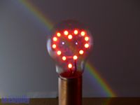
For Valentine’s Day this year I have created an led heart in a light bulb lamp.
LED Heart template download:
Led heart in a light bulb template (2423 downloads )
Parts required
The parts required for this project are:
- Clear incandescent or halogen light bulb. Fluorescent bulbs are not suitable.
- Cork
- Fourteen red 3mm leds
- Flexible copper wire (2×13 speaker wire)
- Stiff solid copper wire (house lighting wire)
- Heat shrink tubing
- 22mm diameter copper pipe. You could substitute plastic or cardboard pipe covered with copper foil.
- Wooden block
- 200 ohm 1/4 Watt resistor
- 9 volt battery
- 9 volt battery connector
- XL6009 Step-up switch mode boost module with an output voltage of 30 volts
Tools required
The tools that you will need are:
- Rotary tool such as a Dremel
- Small grind stone attachment for the rotary tool
- 1mm & 2mm drill bit
- Pliers
- Thin nose pliers
- Soldering iron & solder
- Helping hand
- Drill
- 25mm or 1″ holesaw
- 6mm or 1/4″ wood drill bit
- Small rotary sanding attachment for the rotary tool
- Wood saw
- Sanding tool and/or sandpaper
- Heat gun (a hair dryer works)
- Multimeter that can measure 35 volts DC
Prepare the light bulb
The first task is to open up and clean out the light bulb.
Glass is incredibly sharp and can fly some distance when it breaks, therefore careful handling of the bulb is necessary.
- If you are using a bayonet type bulb with two contacts, then drill through the bulb contacts using a drill and a 2mm drill bit. The bulb contacts should just come away.
- If you are using a screw type bulb, then you can grip the contact with pliers and pull the contact off.
- Using thin nose pliers break away the insulator from the bulb.
- Carefully break through the glass and pull the element out of the bulb.
- Grind away the remaining internal sharp edges using a grind stone attachment in a rotary tool.
- If the base of the bulb comes apart from the glass during the grinding process then it can be reattached using epoxy adhesive.
- Wash away any debris from the bulb and dry it thoroughly.
Make the led heart
The led heart is formed by soldering individual leds together in series. The heart is made in two sections and these sections are joined later to form the shape of the heart.
The positive + side of each led is identified by a longer lead and the negative – side by the shorter lead.
To make this process easier I have created a template for the led placement and orientation that you can download (see above).
Leds are fairly robust devices, but nonetheless you should try and avoid overheating them during the soldering process.
- Print the led heart template.
- Punch holes in the template to hold the leds.
- Starting on the right hand side of the template and using the holes, solder a string of seven leds together. The long + lead on one led connects to the short – lead on the next led. Follow the polarity marked on the template.
- Now solder a string of 7 leds together on the left hand side of the template again following the polarity indicated on the template.
Solder a flexible wire to join the leds at the top of the heart
- Cut and strip the insulation from a short length of flexible wire.
- Twist the strands of the flexible wire together.
- Wrap the flexible wire around the unused leads on the leds at the top of the heart.
- Solder the flexible wire in place.
- Trim the excess wire with wire cutters.
Solder stiff supply wires to the led heart
- Cut a length of stiff solid house wire.
- Strip the insulation from the house wire leaving bare copper wire.
- Bend the stiff copper wire over to form a U shape.
- Solder the two ends of the stiff copper wire to the unused leads on the bottom two leds.
- Cut the loop off from the stiff copper wire to make two separate stiff leads.
This is a good time to test that the led heart works. The section on the power supply gives details on how to power it.
Insert the led heart into the bulb
Now we come to the seemingly impossible task of inserting the led heart into the light bulb.
- Fold the led heart in half, making use of the flexible wire link as a pivot point. The shape of the led heart should now resemble a hook.
- Feed the folded led heart into the base of the bulb, carefully manipulating it into the body of the bulb.
- Making use of the stiff wires attached to the led heart, open up the led heart.
Fit the bulb base
The base of the light bulb is made from a cork that fits tightly into the bulb.
- Drill two holes through the cork. The drill diameter (1mm) should be slightly smaller than the diameter of the stiff wires on the led heart.
- Push the two stiff wires from the led heart through the holes in the cork.
- Push the cork into the base of the light bulb.
- Twist the stiff wires to manipulate the led heart into the correct position.
The cork makes for a tight fit, but for a more permanent solution you can secure it with epoxy adhesive.
Solder the power supply cable to the bulb
The power supply cable is made from twin 2×13 speaker wire. One of the wires has a black stripe, the other is plain. The wire with a black stripe should be connected to the negative side of the bulb and the plain wire to the positive side of the bulb. The polarity of the bulb connections can be determined from the led template.
- Cut an appropriate length of wire so that you can position the lamp in the desired location.
- Strip insulation from each of the speaker wires.
- Tin the speaker wires with the soldering iron.
- Cut two lengths of heatshrink tubing and place over the speaker wires.
- Use the helping hand to stabilise the bulb and and also to act as a heatsink on the bulb side of the stiff wires.
- Solder the speaker wires to the stiff wires.
- Push the heatshrink tubing over the soldered connections and shrink it with a heat gun.
Make the lamp base
The lamp base is made from a block of wood from a recycled pallet and a length of 22mm copper tubing.
- Cut a hole through the block of wood using a 1″ or 25mm holesaw.
- Using a rotary sanding attachment in a rotary tool, enlarge the top half of the hole until the copper tubing fits snugly.
- Trim the wood to length using a saw.
- For the power cable, drill a 6mm or 1/4″ hole through one side of the wood to the hole.
- Sand the block of wood and finish as desired.
Assemble the lamp
- Thread the power supply cable from the bulb through the copper tube.
- Push the base of the bulb into the copper tube.
- Thread the cable through the large hole in the wood block.
- Thread the cable through the smaller hole in the side of the wood block.
- Pull all of the slack cable through the wood block.
- Insert the copper tube into the wood block.
Build the power supply
The led heart consists of fourteen 2 volt leds in series which means that it needs a power supply greater than 28 volts. The leds are constant current devices that usually operate at 20mA. To reduce the heat in the light bulb and also to increase the life span of the leds it is a good idea to run them at a lower current level of 10mA. The light output from the leds at 10mA is more than enough and the heart effect is improved at lower light levels.
To limit the current to 10mA, a 220 ohm resistor is placed in series with the leds and the supply voltage is set to 30 volts.
- Cut the positive (plain) power wire from the led lamp.
- Strip insulation from both ends of the cut wire.
- Tin the stripped wires with a soldering iron.
- Place heatshrink tubing over both wires.
- Solder the resistor between the wires.
- Cover the soldered connections with the heatshrink tubing and shrink with a heat gun.
The power source is a 9 volt battery and this is boosted to 30 volts by an adjustable step-up switch mode boost module based on an XL6009 chip.
- Solder the 9 volt battery connector positive (red) lead to the module’s positive +IN terminal.
- Solder the 9 volt battery connector negative (black) lead to the module’s negative -IN terminal.
The XL6009 module has an adjustable voltage output and it must be set to 30 volts before connection to the led lamp.
- Connect the 9 volt battery to the battery connector.
- Set the multimeter to read dc voltage with a range that can read 35 volts.
- Connect the multimeter to the output terminals +OUT and -OUT of the module.
- Adjust the output voltage to 30 volts by turning the screw on the module’s blue potentiometer.
Finally connect the module to the lamp.
- Disconnect the 9 volt battery from the battery connector.
- Solder the positive (plain) wire from the led lamp to the module’s positive +OUT terminal.
- Solder the negative (striped) wire from the led lamp to the module’s negative -OUT terminal.
Test the lamp
The only thing left to do now is to test the lamp by plugging the 9 volt battery into the battery connector.
If the light output from the led lamp is too high then you can reduce it by turning the screw on the blue potentiometer.