
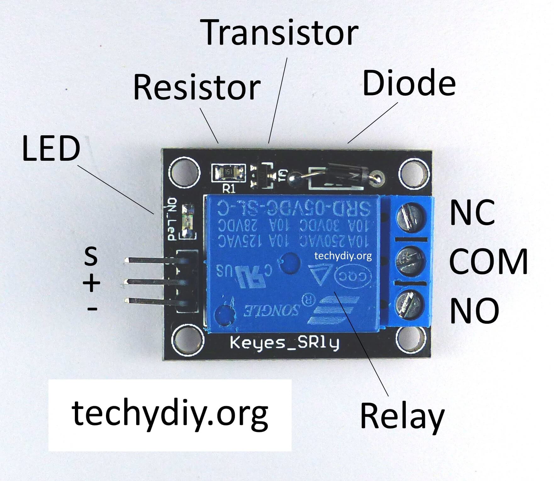
The Keyes SR1y relay module
Maximum 10A 250V AC
Maximum 10A 30V DC
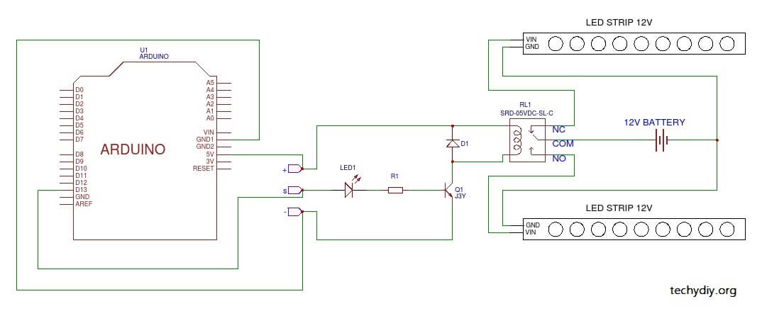
The + pin is connected to a +5V DC power supply.
The – pin is connected to the power supply ground.
The S pin connection is the input.
The relay and led will operate when a high signal is present on the S input.
The diode across the relay coil is there to prevent back emf from the coil.
The transistor provides current gain and a small input current can switch the relatively large current required to operate the relay coil.
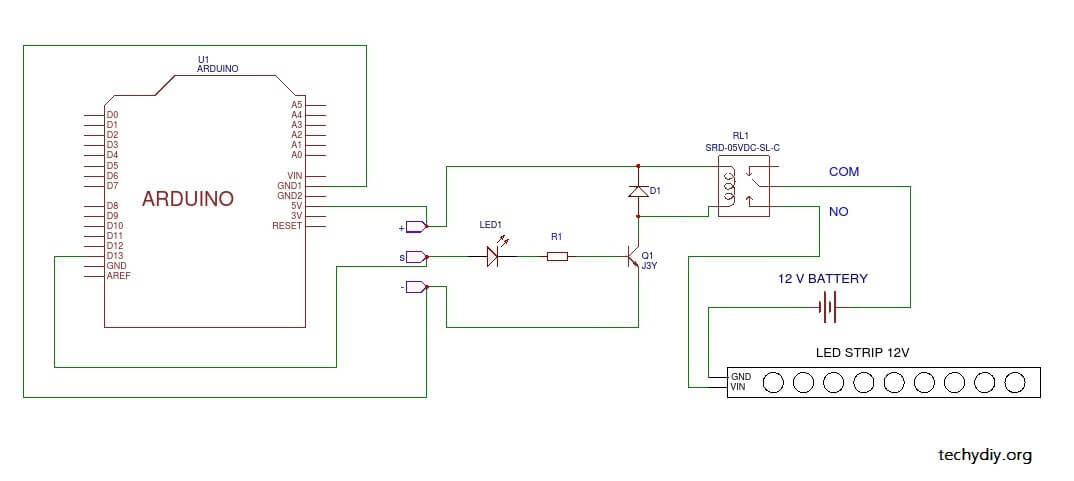
Keyes SR1y relay module input connection to an Arduino Uno

The S input of the relay board can be connected to any of the Arduino Uno
// Keyes SR1y relay blink sketch

#define RELAY_ON 1			// Define relay on pin state
#define RELAY_OFF 0			// Define relay off pin state

#define Relay  13  			// Arduino pin where the relay connects

void setup()
{
  digitalWrite(Relay, RELAY_OFF);      // initialise the relay to off
  pinMode(Relay, OUTPUT);
  delay(1000);
}

void loop() 				// Turn the relay on and off in sequence
{
  digitalWrite(Relay, RELAY_ON);	// turn the relay on
  delay(1000);               		// wait

  digitalWrite(Relay, RELAY_OFF);	// turn the relay off
  delay(1000);              		// wait
}
Relay Load connections
Flashing Led light strip
A 12v led light strip


The relay will operate when the output from the Arduino is high and turn on the led strip.
Dual alternate flashing LED light strips
Adding another led light strip to the NC (normally connected) contact of the relay creates alternate flashing led strips.
It seems to be very useful relay but where from it can be purchased ?
banggood for example