Relays are electrically operated switches, which allow a low-level electrical signal to control a separate larger electrical voltage or current.
Several types of relays are available to suit different applications, including reed relays


Relay Construction
A relay is an electromechanical device that consists of a number of parts, including the Coil, core, armature, yoke, contacts, spring and the push-rod.
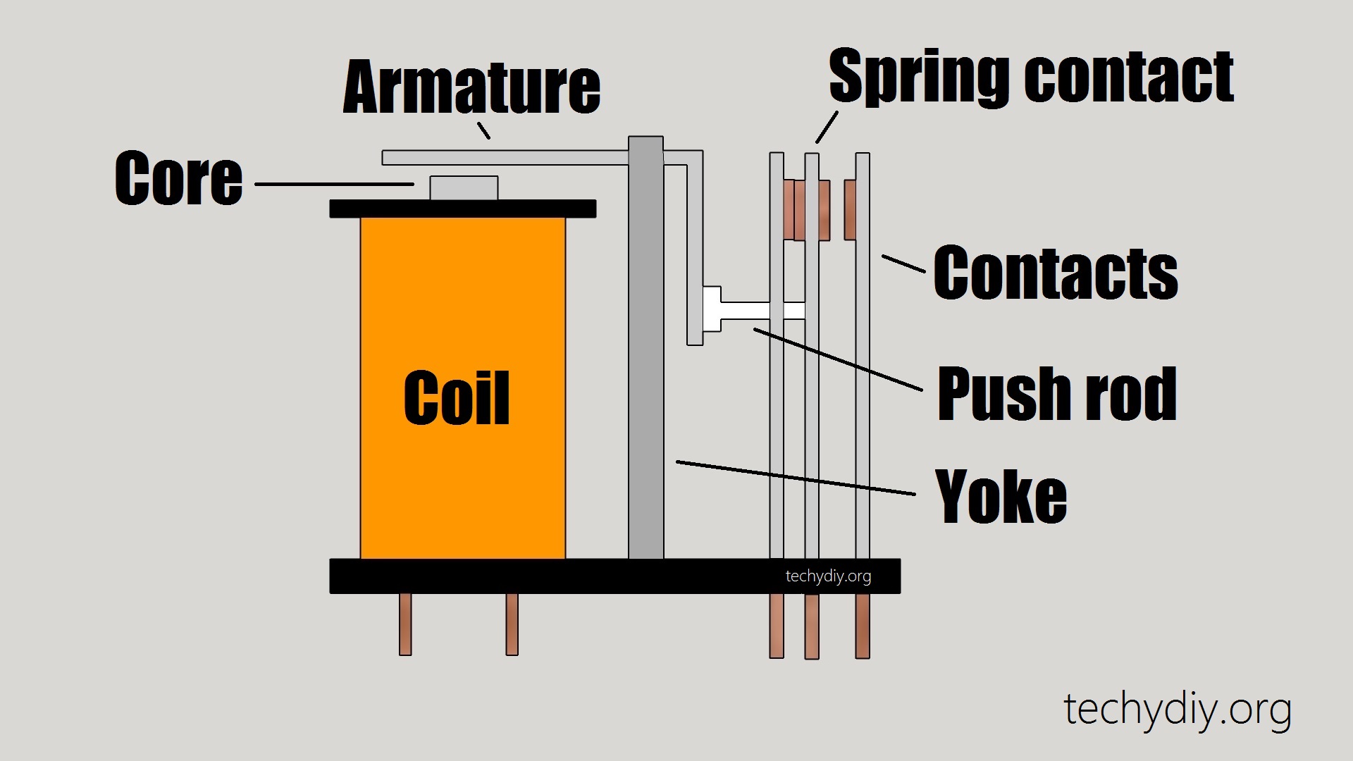
Relay Operation
When a voltage is applied to the coil, a current passes through it and this creates a magnetic circuit which includes the core, armature and the yoke.
The core attracts the armature, which pivots and presses the push rod against the common contact, breaking the electrical connection with one contact and making the electrical connection with the other contact.
When the voltage is removed from the coil the magnetic attraction of the armature to the core ceases. A spring then returns the contacts, pushrod and armature to the initial position. In this example, the common contact also acts as the spring, but in other relays, a separate spring is employed.
Relays contacts – Break, Pole & Throw
Relay contacts are available in several different combinations specified as pole and throw.
Poles are the number of separate electrical circuits.
Throw is the number of contact positions for each circuit.
SPST – Single Pole Single Throw
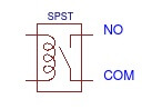
This is a simple on-off switch.
SPDT – Single Pole Double Throw
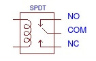
This is a single changeover switch.
DPDT – Double Pole Double Throw
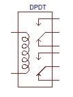
This is two separate changeover switches that operate at the same time.
4PDT – Four Pole Double Throw

This is four separate changeover switches that operate at the same time.
Break
Relay contacts can be specified to break before make or make before break
With break before make the common contact disconnects (breaks) with the first contact before connecting (makes) with the second contact.
Make before break – the common contact remains connected to the first contact until after connecting to the second contact. It then disconnects from the first contact.
Normally open (NO), normally closed (NC) & common contacts (COM)
The electrical circuit between COM and NO contacts is made when power is applied to the coil.
The electrical circuit between COM and NC contacts is broken when power is applied to the coil.
Contact material
Relay contacts can be made from different materials that make them suitable for different types of switching. Switching a low-level signal requires a different contact material to be used than when switching a high power load.
Minimum switching load
For low-level loads, a minimum switching load is specified. For example 10mA at 5VDC.
Maximum switching load
This is normally specified in VA for AC and Watts for DC.
The maximum for inductive loads will be lower than the maximum for resistive loads.
Maximum switching voltage
Specified in volts this will be different for AC and DC.
Maximum switching current
Specified in amps.
Coil
The coil specification will include the nominal voltage, maximum voltage, nominal current, resistance, pull in voltage and drop out voltage.
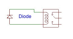
Coil back-emf, voltage spike & snubber circuits
When there is a change of current in the relay coil due to it being powered off, the inductor will try and maintain the current by generating a voltage spike. This voltage spike can be hundreds or thousands of volts, which can harm sensitive electronic components such as transistors.
To prevent the voltage spike, a snubber circuit can be employed. Usually, this takes the form of a clamping or free-wheeling diode
The downside to this arrangement is that the switch off time for the relay will be increased. To improve this, a zener diode
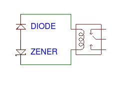
Other options for snubber circuits include a resistor, a series resistor and capacitor, MOV (Metal oxide varistor) and TVS (Transient Voltage Suppressor).
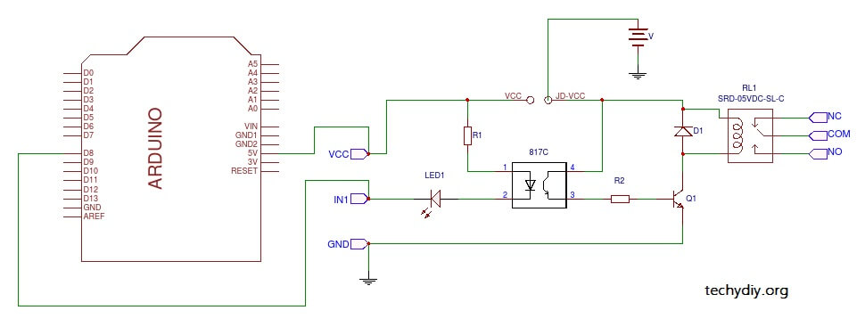
Relay driver circuit
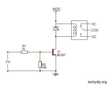
To drive the relay from a low power signal a transistor is often used to switch the relay.
No voltage applied to Vin – Current does not flow between the base and emitter of the npn transistor and current does not flow between the collector and emitter, so the relay coil is not energised.
Positive Voltage applied to Vin – Current will flow between the base and the emitter of the npn transistor and this allows current to flow between the collector and emitter which energises the relay coil. The transistor has gain, so only a small amount of current is required to drive a large amount of current to energise the relay coil.
A free wheeling diode is placed across the coil to suppress voltage spikes.
Relay modules
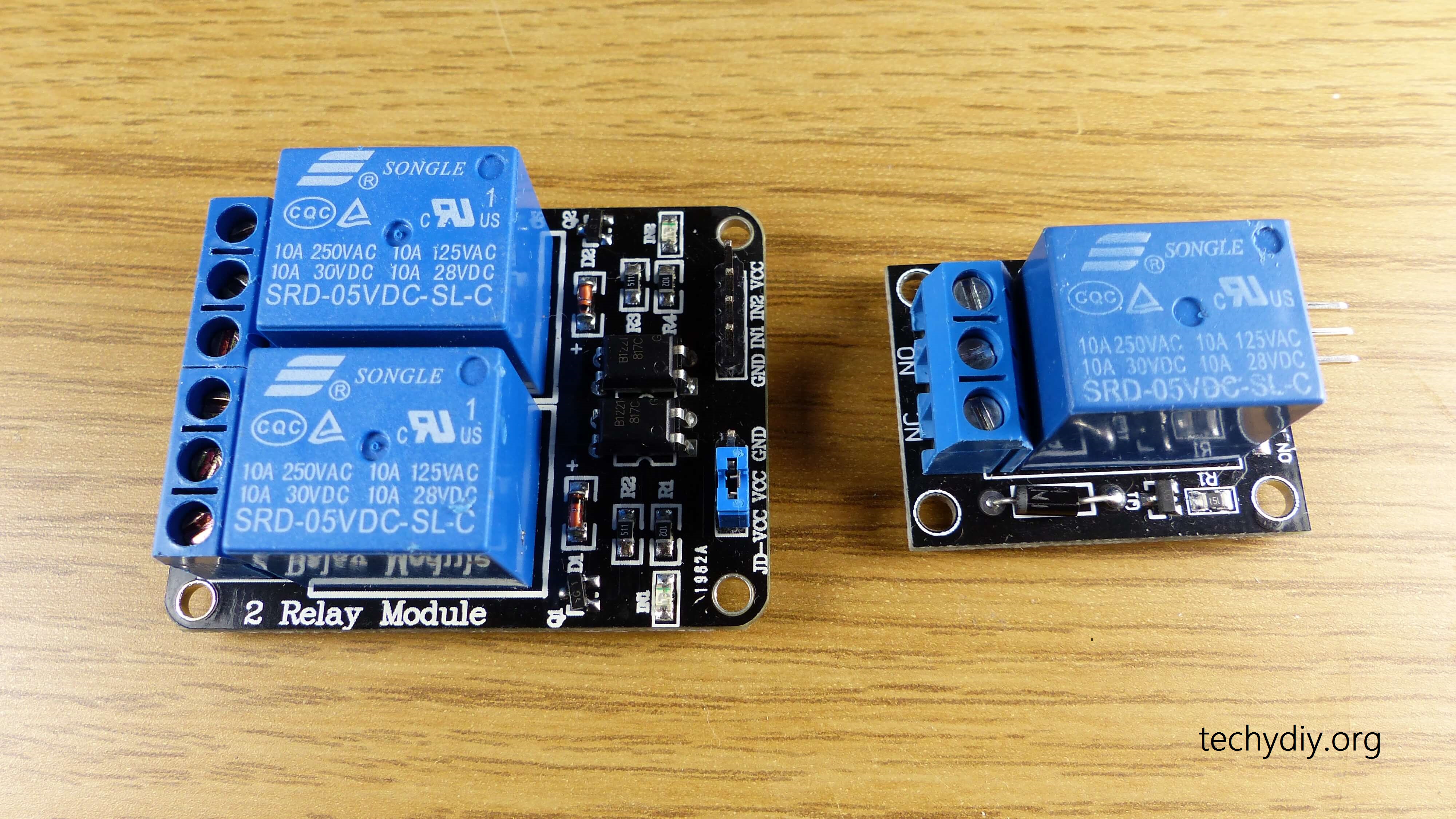
Relay modules


The modules
The relays are usually the same type: SONGLE SRD-05VDC-SL-C
10A 250VAC
10A 30VDC

There are generally two types:
Simple relay modules without an optoisolator

The simpler type of relay module
This type of module has active high switching, which means that a positive voltage on the input will switch the relay on and a low signal or connection to ground will turn it off.
Relay modules with an optoisolator
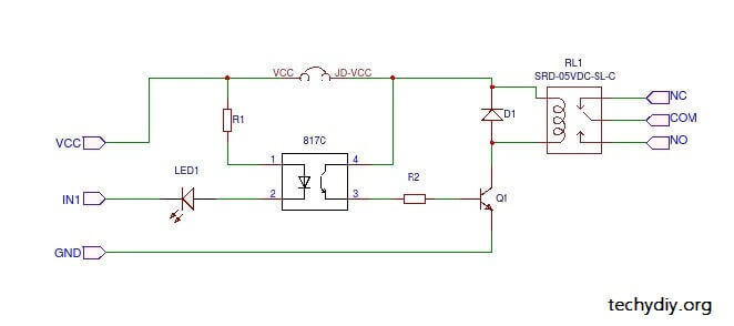
The more complex type of relay module
To isolate the circuits the jumper between VCC and JD-VCC is removed and a separate power supply connected between JD-VCC and GND to power the relay.
The connections to the input circuit are VCC and IN1.
This type of module has active low switching, meaning that the relay is enabled when the input signal is low and deactivated when the input signal is high.