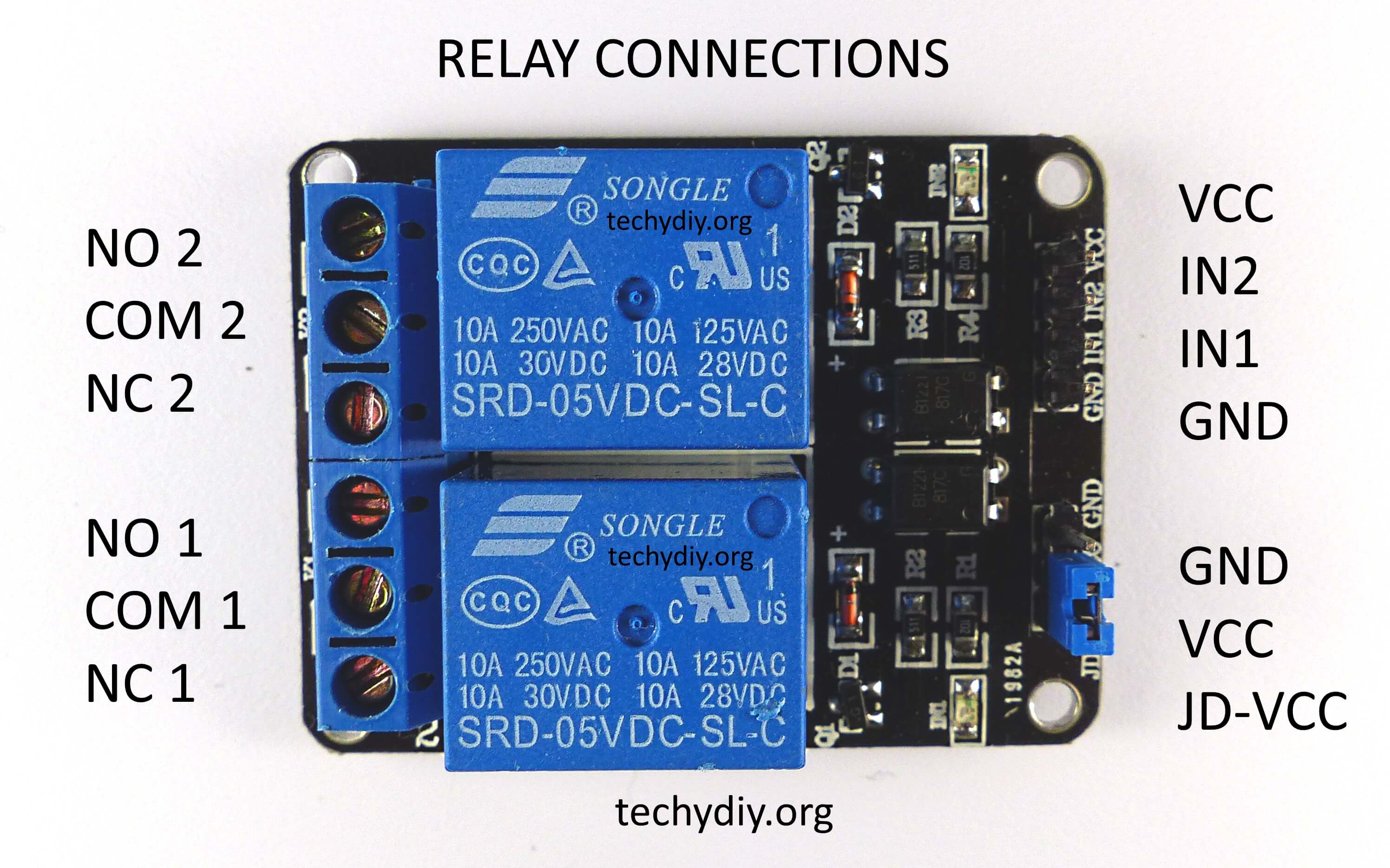
This is a dual relay module using the usual Songle SRD-05VDC-SL-C relays
.
The module has two spdt relays which can switch:
10A 250V AC
10A 30V DC
Although this would be less for inductive loads.
The module is an active low device, which means that the input must be low to switch the relay on.
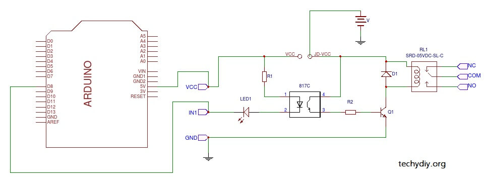
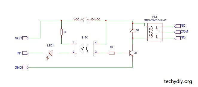
The module also contains 817c optocouplers and the input circuit can be isolated from the relay circuit by removing the JD-VCC jumper and providing a separate power supply for the relay.
The following circuit diagram shows the relay module with the input isolated from the relay.
 // Opto-isolated relay blink sketch
|
1 2 3 4 5 6 7 8 9 10 11 12 13 14 15 16 17 18 19 20 |
#define RELAY_ON 0 // Define relay on pin state #define RELAY_OFF 1 // Define relay off pin state #define Relay 13 // Arduino pin where the relay connects void setup() { digitalWrite(Relay, RELAY_OFF); // initialise the relay to off pinMode(Relay, OUTPUT); delay(1000); } void loop() // Turn the relay on and off in sequence { digitalWrite(Relay, RELAY_ON); // turn the relay on delay(1000); // wait digitalWrite(Relay, RELAY_OFF); // turn the relay off delay(1000); // wait } |
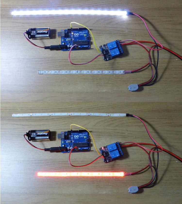
The following photo shows the Arduino Uno running the sketch listed above with the relay wired to two led strips
and a 12v battery
.


Is it possible to post the values of R1 and R2? Also the type of transistor Q1? Also, why is there a optocoupler at all? in what situations is it needed? Thre relay is already separated from the mains voltage.
If your logic board is 3.3v and can not power the magnet of the relay. You dont want to risk sending more voltage into say an 8266 than you need or risk burning it out.
I’m pretty sure R1 is 1k and R2 is 510 and Q1 is a J3Y.
But there are 2 Grounds on the actual board and the schamtic only shows one. Which ground do you use? Does it matter?